Phasor Diagram Of Pure L Circuit
Phasor circuit shown draw diagram values determine figure solved frequency operating Rl circuit : working, phasor diagram, impedance & its uses Rlc series network: impedance, current, power factor, phasor diagram
Why is the inductive reactance or capacitive reactance phasor on the
Rl circuit : working, phasor diagram, impedance & its uses Ac supply to pure resistor (theory, phasor & waveforms 5.draw the phasor diagram of the circuit (show on the
Rl circuit : derivation, phasor diagram, impedance & its uses
Pure resistive circuit ac purely waveform power instantaneous resistor voltage phasor current supply shown figureSolved: use the phasor diagram for a parallel r?l?c circui... Phasor circuits diagrams rl circuit rcPhasor iin vl.
What is rc series circuit? phasor diagram and power curvePhasor resistive circuits Phasor diagrams for ac circuits / phasor diagram at r, l and c in acSeries circuit rc phasor diagram vector impedance draw phase circuits power ckt voltages multiply why which capacitor finding when curve.

Circuit rl phasor derivation circuitglobe impedance diagrams
Phasor diagram for lrc circuitPhasor diagram circuit lrc Circuit phasor diagram rl parallel uses working its voltage relationship rcPhasor circuits circuit rl resistors inductors capacitors interpret.
Circuit diagram phasor rl series uses working its impedanceInductive waveform pure phasor purely curve compressor explanation circuitglobe consumed Phasor diagrams chapter circuit resistive ppt powerpoint presentationPhasor diagram circuit lr ac teaching eng ed.
Phasor diagram parallel circuit current use figure following find part source solved
Phasor diagram voltageSolved 1. draw the phasor diagram for the circuit shown in Phasor rl inductor explaination difference begingroupPhasor diagrams for ac circuits / phasor diagram at r, l and c in ac.
Why is the inductive reactance or capacitive reactance phasor on theLr circuit, with phasor diagram Phasor diagram for pure resistive circuits- magic marksWhat is a pure inductive circuit?.

Circuit phasor series rlc reactance inductive diagram voltage capacitive parallel analysis impedance vector electrical reference source constant axis imaginary why
.
.


Solved 1. Draw the phasor diagram for the circuit shown in | Chegg.com

5.Draw the phasor diagram of the circuit (show on the | Chegg.com

PPT - Chapter 31 PowerPoint Presentation, free download - ID:6368460

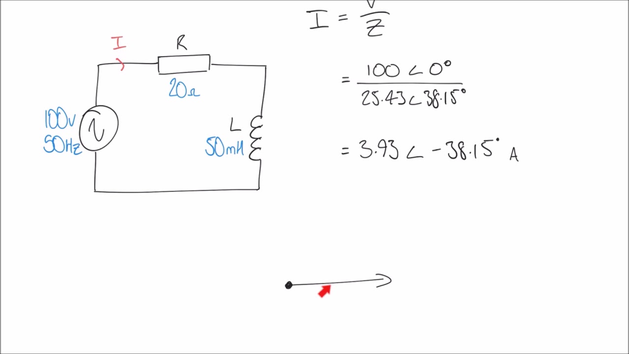
RL Circuit : Derivation, Phasor Diagram, Impedance & Its Uses
Phasor Diagrams For Ac Circuits / Phasor Diagram at R, L and C in AC

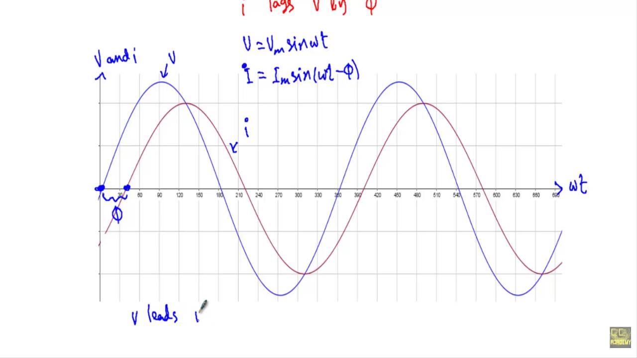
Phasor diagram for LRC circuit - YouTube

inductor - Explaination on phasor diagram for RL circuit? - Electrical

What is RC Series Circuit? Phasor Diagram and Power Curve - Circuit Globe